


A6A3 Last Converter Replacement
Note
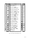
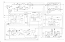
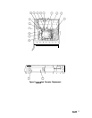
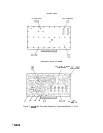
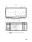
For location of hardware and cables referred to in this procedure, see Figure 2.
Removal
1. Remove ac line cords and RF Section bottom and right side covers.
2. Disconnect cables @: three from top of A6A9 Phase Lock assembly and two from A6A12
YTX Driver board.
3. Remove A6 RF Module PC cover plate by removing six screws
0.
4. Remove A6A9 assembly and
A6Al0,
A6Al1,
and A6A12 PC boards from the A6 RF
Module. It is not necessary to disconnect the two cables (green and yellow) from the front
side of the A6A9 Phase Lock assembly.
5. Disconnect the following cables from the A6A3 Last Converter:
2 (red) cable
@
1 (brown) cable
@
81 (gray/brown) cable
@
6. Remove two screws
QJ
and remove A6A3 Last Converter
@
from RF Module.
Installation
7. When installing the A6A3 Last Converter, push Last Converter board into A6A13
Motherboard PC connector, replace two screws
0
and reconnect cables disconnected in
step 5.
8. Replace PC boards removed in step 4. Reconnect 5 (green) and 4 (yellow) cables to A6A9
Phase Lock if they were removed during removal of A6A3.
9. Replace and secure A6 RF Module PC board cover with six screws
0.
10. Reconnect cables
(iJ
to A6A9 Phase Lock and A6A12 YTX Driver. Cables are color-coded
and color codes are marked on PC board cover.
11. Replace bottom and right side covers on RF Section. Reconnect ac line cords.
4
A6A3