


A7Al
A7Al
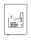
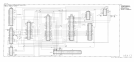
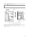
Reference Phase Detector, Circuit Description
The
A7Al
Reference Phase Detector contains the frequency divider, phase detector, and
integrating amplifier for the 100 MHz Reference phase-lock loop. Basically, 100 MHz from
the A7A2 VCXO is divided by 10 and compared to the 10 MHz frequency reference by the
phase detector. The error voltage from this comparison is fed back to the VCXO to keep its
frequency locked to 10 times that of the frequency reference. The bandwidth of the reference
phase-lock loop is 100 Hz; the 10 MHz derived from the 100 MHz VCXO must be within 100
Hz of the 10 MHz frequency reference for the loop to lock reliably.
Limiting Amplifier
@
Ul
amplifies and limits the amplitude of the reference signal from the rear panel FREQ
REFERENCE input. For proper operation of the 100 MHz Reference phase-lock loop, this
signal should be 5 MHz
f25
Hz or 10 MHz
f50
Hz at a power level of 0
dBm
to
+lO
dBm.
The internal A22A2 10 MHz Quartz Crystal Oscillator provides a stable, high spectral purity
10 MHz frequency reference at a power level of at least
+7
dBm
at the rear panel FREQ
REFERENCE output. A short BNC jumper cable is normally connected between the FREQ
REFERENCE input and output jacks to route the internal frequency reference signal to
the 100 MHz Reference phase-lock loop. The spectral purity of the FREQ REFERENCE
input signal directly affects the instrument phase noise performance. The internal frequency
reference remains off during instrument warmup (from a cold start) until it reaches thermal
equilibrium.
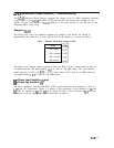
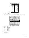
Pulse Generator
@
U2D is biased with feedback resistor RlO to further limit the 10 MHz to a well-shaped square
wave and set the proper logic levels for digital buffer U2C. U2A and
U2B
generate narrow
pulses, the width being the gate delay of U2A plus the delay from
Rll
and C5. When the
output of U2C goes low, the output of
U2B
goes high after one gate delay (of U2B). After a
delay due to
Rll,
C5 and U2A gate delay, the output of U2A goes high which causes
U2B
output to return low again, thus generating a narrow pulse.
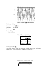
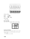
Phase Lock Sampler
@
The phase lock sampler performs the function of phase detector. The 10 MHz pulses from the
buffer amplifier are applied to the primary of
Tl
which causes CR3 and CR4 to turn on for
the duration of the pulses. This samples the divided by 10 VCXO frequency and stores this
voltage on C36. When the loop is locked, the feedback due to the complete phase-lock loop
forces this voltage to be nearly zero. When the loop is unlocked, this voltage may be zero or
varying, depending on the reason for unlock.
A7A1
1