


A6A3
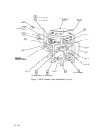
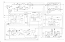
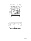
A6A3 Last Converter, Circuit Description
The Last Converter has three main purposes:
1. Converting the 321.4 MHz IF signal from the A6 RF Module down to 21.4 MHz for
processing by the IF-Display Section.
2. Providing the means for correcting for variations in conversion loss versus frequency in the
input circuitry.
3. Filtering out 278.6 MHz image response.
The Last Converter consists of 11 basic elements. They are a 321.4 MHz amplifier, a 321.4
MHz
bandpass
filter, a 321.4 to 21.4 MHz converter a 21.4 MHz preamp, two pin diode
attenuators, two pin diode controlled variable gain amplifiers, an output stage, a temperature
compensation circuit, and power supply filtering.
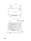
Power Supplies
@
The power supply filtering consists of series inductors and shunt capacitors (L21 to L24
and C49 to C53). In addition to this, R38 and
VRl
provide a 6.2 V source used for biasing
transistors.
321.4 MHz Amplifier
@
The 321.4 MHz amplifier consists of Q8 and its associated circuitry. Q7 provides bias for
QS
by setting the base current.
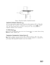
321.4 MHz Bandpass Filter
@
The 321.4 MHz amplifier drives the 321.4 MHz
bandpass
filter which consists of L4 to L8
and C8 to C12. This filter is made up of five LC tank circuits coupled magnetically and
capacitively. Capacitive coupling occurs through PC board traces on the circuit side of the PC
board. Coupling into and out of the filter is done with tapped inductors L4 and L8. The filter
is tuned by means of C8 to C12. This filter rejects the 278.6 MHz image response.
321.4 to 21.4 MHz Converter
@
The 321.4 MHz filter drives the 321.4 to 21.4 MHz converter. This converter consists of a
packaged double-balanced mixer,
Ul.
The 300 MHz LO for this converter comes from the
A6A9 Phase Lock.
A6A3
1