


A7Al
Reference Phase Detector, Troubleshooting
The
A7Al
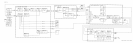
Reference Phase Detector compares the output of the 10 MHz Frequency Standard
to the output of the A7A2 100 MHz VCXO and provides the tuning drive voltage for the
VCXO. A phase lock detector in
A7Al
indicates to the main processor (A15) the state of the
Reference Phase Lock Loop.
Samplers
@,
@
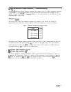
The Phase Lock and Lock Indicator Samplers are identical. The diodes are biased to
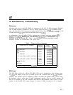
approximately the same level in each. The dc bias on the diodes is as shown in Table 1.
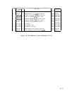
Table 1. Sampler Diode Bias Voltage Levels
I
Diode
CR3 Anode
CR4 Cathode
CR5 Cathode
CR6 Anode
The Phase Lock Sampler output (junction of R32 and R34) is 0.0 V when locked or with no
10 MHz reference, and approximately
+O.l
V with no 100 MHz input. The Lock Indicator
output (junction of R25 and R23)
is -1.5 V when locked, 0.0 V with no 10 MHz reference,
and approximately
+0.2
V with no 100 MHz input.
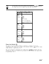
45’ Phase Lead Amplifier
@I
and
45”
Phase Lag Amplifier
@
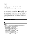
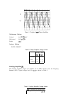
The Phase Amplifiers shift the 100 MHz VCXO signal, which has been divided by 10 by U3,
+45” and -45” respectively. Figure 1 is typical of the waveforms at the collectors of
Ql
and
Q2.
The dc voltages for
Ql
and
Q2
are as shown in Table 2. The waveform of
Ql
leads the
waveform of Q2 by approximately 20 nanoseconds in Figure 1.
A7A7 3