


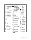
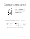


Schematic Symbols for Digital Integrated Circuits
The following is a guide to the symbols used for digital or logic ICs in this manual. The
symbology is based upon American National Standard ANSI Y32.14, Graphic Symbols for
Logic Diagrams (Two-State Devices), but does not strictly follow the standard. Figure 6
should be consulted for the explanation of digital IC symbols used in Sections VIII and IX.
Definitions
Logic Element. The part or parts of a logic device symbol having a well-defined logic function
(OR, AND, FLIP-FLOP,
and so on) and one or more outputs. The inputs of a logic element
may be data or control inputs; the outputs are data outputs.
Control Block. The part of a logic device symbol to which all logic lines common to a group of
logic elements are connected. Lines connected to a control block are control lines.
Function Label. The notation within a logic device symbol that denotes its overall logic
function (counter, shift register, multiplexer, and so on)
Line Label. The symbol or abbreviation associated with an output or input line that defines
the action of the line.
Indicator Symbol. A symbol associated with an input or output line which defines the active
state or special characteristics of the line.
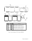
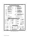
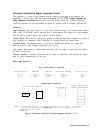
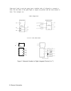
Basic Logic Symbols
Dist nctive-Shape Symbols
Amplifier/Buffer
AND Gate OR Gate EXCLUSIVE OR Gate Schmitt Trigger
Rectangular Symbols
General Logic Element
I
I
*
1
*
Logic Elements with
Control Block Comnon Control Block
*
El
NOTE :
An asterisk indicates the
location
of the function label.
If elements
sharing control lines are widely separated, each element will have a
separate
control block.
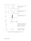
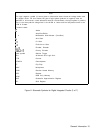
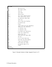
Figure 6. Schematic Symbols for Digital Integrated Circuits (1 of 7)
General Information 13