


A6All
A6All
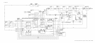
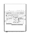
Slope Generator, Circuit Description
The slope generator takes a voltage which is proportional to YTX frequency and produces a
current to control the slope attenuator in the A6A3 Last Converter, which compensates for
conversion loss variations of the input mixer within each frequency band. The slope generator
also has circuitry which decodes bandswitch and attenuator settings, produces pulses for
the sample and hold, and hysteresis circuits in the A6A12 YTX Driver, produces the YTX
peaking signal for the YTX Driver, and a signal to switch in the filter capacitor on the A6A7
YTX Current Driver.
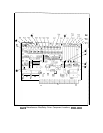
Bandswitch and Attenuator Decode
@
U9
is a hex latch which receives six lines from the 50-wire Instrument Bus and a strobe,
LCK2, which goes low when the six lines have valid A6 RF Module information. Three of
the latch outputs have attenuator setting information and go to the A6AlO Miscellaneous
Bias/Relay Driver. The other three lines have bandswitch information which is decoded by
U3A and U3B.
U3B
decodes the low band (Band A, 0 to 2.5 GHz) and the external mixer band (Band F).
When pin 2 of
U9
is high and pin 12 is low, Band A is selected. The output of
U3B
is high,
turning
Q22
on, bringing the collector of Q22 low. This turns
Q19
off, bringing the collector
of
Q19
(LO BAND) high. This information goes to the A6AlO Miscellaneous Bias/Relay
Driver to control the
A6Al
RF input switch. Q20 inverts the signal and drives amplifier A4A,
producing a signal which is approximately
+17
V when Band A is valid and approximately
-8 V otherwise. This signal is used throughout the
A6All
Slope Generator. When pins 2 and
12 of
U9
are both high, Band F is active. The output of
U3B
is low, turning
Q22
off, and
bringing the collector of
Q22
(and Band F line) high. At the same
time,me,
Q19
turns on,
bringing the LO BAND line low.
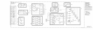
U3A decoder is enabled when pin 2 of
U9
is low. Pins 5 and 12 of
U9
have coded information
giving harmonic numbers as shown in Table 1.
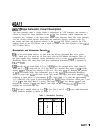
Table 1. Bandswitch Decoding
Band B2 (pin 12)
Bl
(pin 5)
N
B
0
1
1
C
1
0
2
D
1 1
3
E
0 0
4
A6A11
1