


Transformer Replacement
Note
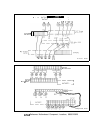
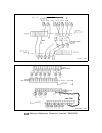
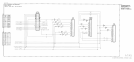
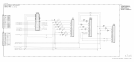
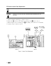
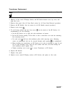
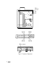
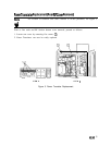
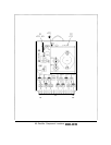
For location of hardware and cables referred to in the procedure, see Figure 2.
1. Remove ac line cords, IF-Display Section, and RF Section bottom cover, top cover, and
right side cover.
2. Remove front panel. (See A5 Front Panel section for A5 Front Panel Removal procedure.)
3. Remove A6 RF Module. (See A6 section for A6 RF Module removal procedure.)
4. Remove seven screws
Q).
5. To avoid losing washers and nuts from screws
@
into the interior of the RF Section, it is
recommended to do the following:
a. Set the RF Section on its right side with transformer on bottom.
b. Set the RF Section partially off the table so that a screwdriver can reach the remaining
four mounting screws.
c. For each screw
@
hold nut with needlenose pliers while removing screw. Mounting
screws on motherboard side can be accessed through small opening @ on motherboard.
d. When installing new transformer, set RF Section on its side as described in steps 5a and
5b. For each mounting screw, align nut and washers with hole, and while holding nut
with needlenose pliers, tighten screw.
e. Tighten remaining seven screws
(iJ
to secure Transformer to RF Section.
6. Replace RF Module.
7. Replace front panel.
8. Replace covers, attach IF-Display section to RF Section, and replace ac line cords.
AalA
3