


A7A3
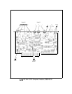
A7A3 M/N Phase Detector, Circuit Description
The M/N phase detector has two programmable frequency dividers: an M divider and an
N divider. M and N are integer numbers which give the ratio of divider input frequency to
divider output frequency. This is the divide number. The input to the N divider is 20 MHz;
the M divider input is the difference frequency between the M/N VCO (355 to 395 MHz) and
400 MHz. The two divider outputs are compared in a phase/frequency detector. The detector
output is amplified and applied to A7A4 M/N Output where it is used to tune the M/N VCO.
In general, the M/N output frequency (from A7A4) is (200 to 10 M/N) MHz. The M/N VCO
frequency is twice the M/N output frequency. The spectrum analyzer frequency diagnostics
(displayed by
(SHIFT)
[MKR~REF LVL)) show the M number, N number, and M/N frequency.
The fifth line of diagnostics contains three integers; the second integer is the M number, and
the third integer is the N number. The next (sixth) diagnostic line gives the M/N output
frequency in MHz (177.5 MHz to 197.5 MHz).
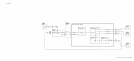
TTL
+
ECL Level Translators
@
The numbers to program the frequency dividers come from Al2 Front-Panel Interface in
binary at TTL levels. U3, U13, and U17 shift these to ECL levels which are approximately
-0.9 V logic high and -1.7 V logic low.
Nl
and Ml designate the least significant bits.
N Divider
@
and M Divider
@
The M and N dividers are virtually identical. Basically, the four most significant bits of N
(three bits for M) N3, N4, N5, N6 load a counter U6. It counts down to two and is reloaded
on the next clock pulse. The two least significant bits,
Nl
and N2, control pulse swallowing
logic which causes the counter to count down to 1 instead of 2 before reloading. The logic
determines the proper number of extra pulses to be swallowed to effect the proper divide
number.
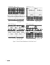
For troubleshooting, it is helpful to set the M and N numbers equal in a 1 MHz span using the
frequency diagnostics explained above. Waveforms at corresponding points in the two dividers
can then be compared to pinpoint the problem.
Mixer
@)
Q3 is an amplifier which drives the LO port of the mixer Q24. It supplies about
+5
dBm
over
the 355 to 395 MHz range. The output of the mixer is the difference between 400 MHz and
the M/N VCO frequency which gives an IF frequency between 5 and 45 MHz. The IF level is
about -17
dBm.
A7A3
1