


Al8
Al8
Negative
Regulator,
Circuit
Description
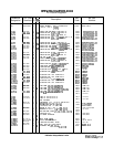
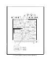
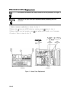
Al8 Negative Regulator provides -5.2 V, -10 V, and -40 V regulated voltages to the
instrument. All three supplies derive their reference from the
+20
V supply on the Al7
Positive Regulator. The relationship of Al8 to A8 Rectifier, Al7 Positive Regulator, and A23
Motherboard is shown on the A8 schematic.
-10
V
Regulator
@
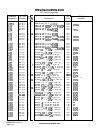
The -10 V supply is referenced to the
+20
V supply by a resistor divider consisting of R5,
R6, and R7 connected between the two supplies. The voltage at the junction of R5 and R6 is
nominally 0 V. Any error is amplified by U2 to drive the series-pass transistor
A23Ql.
The
entire unregulated portion of the supply, including the rectifier diodes and filter capacitor, is
floating; thus the collector of
A23Ql
is typically i-15 V. Current-sensing resistors Rl and R23
are connected between the emitter of
A23Ql
and ground. These resistors, along with R2, R3,
CRl,
and
Ql,
form a current
foldback
protection network.
Overvoltage protection is provided by the -10 V crowbar
BJ
consisting of VR2 and CR26.
Further protection is provided by fuse F3. LED DS2 indicates the presence of an output
voltage.
-5.2
V
Regulator
@
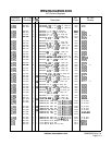
The -5.2 V supply is also referenced to the
+20
V supply by a resistor divider consisting of
R37, R38, and R39 connected between the two supplies. This supply is a double-regulated
supply, as its input is in the regulated output from the -10 V supply. Error amplifier
Ul
drives the pass transistor Q2 via Q3. R32 and R33 are dropping resistors, so the power
dissipation in
Q2
is not excessive. R34, R12, R32, and Q4 provide current
foldback
protection.
Further protection is provided by
Fl.
Overvoltage protection is provided by the -5.2 V
crowbar
@I
consisting of VR4 and CR27. LED DS3 indicates the presence of an output
voltage.
-40
V
Regulator
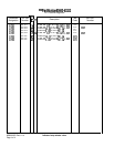
The -40 V supply is referenced to the
+2OV
supply by the voltage divider consisting of R24,
R25, and R26, designed so that the input to the error amplifier U3 is at 0 V. The output
of the error amplifier drives the Darlington connection of
Q5
and the series-pass transistor
A23Q2. The input to the supply is floating, so the collector of A23Q2 is typically at
+lO
V.
Foldback
current protection is provided by R17, R18, R19, and Q6. Further current protection
is provided by the -40 V crowbar
@
consisting of VR3 and CR25. The presence of an output
voltage is indicated by LED
DSl.
A18 1