


Loop
Gain
Switch
(ij
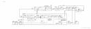
In frequency spans less than 25 kHz (N =
l),
Loop
G
ain
Switch
@
is enabled. The enable
signal HYGH (High = YTO Gain High) is from the Al2 Front-Panel Interface and is high
whenever a frequency span of less than 25 kHz is selected. This high turns on
Q2
which
turns on Q3 which causes
Ql
to saturate.
Ql
then effectively becomes a short, placing R14
between the emitters of Q4A and Q4B. This lowers the emitter resistance by a factor of four,
increasing the gain by approximately 12 dB. This improves phase noise at narrow frequency
spans
(<25
kHz).
Integrator
#l
@
Integrator
#l
produces a ramp output proportional to the amplitude and period of the input.
This integrating action is performed by R16, R21, and
Cl2.
Diodes CR2 and CR3 limit the
upper and lower ramp voltages to one diode drop (approximately 0.6 V). This ramp may be in
either a positive or negative direction depending on the input. When the loop is locked and
the instrument is in zero frequency span, the output is a dc level.
Integrator
#2
@
Integrator
#2
also produces a ramp output but of greater amplitude due to zener diodes
VRl
and CR2. The upper and lower ramp voltages are limited by VRl/C!RG and
VR2/CR7
to
approximately 6.8 V. This corresponds to a capture range of about
&20
MHz, since YTO
sensitivity is -3 MHz/V. Integrating action is performed by R24, R25, and C16. In zero
frequency span, when the loop is locked, the output is a dc level.
Sample
and
Hold
@I
The purpose of the sample and hold
(Ul
and associated circuitry) is to sample the ramp
voltage output of the integrators to tune the YTO frequency, then hold this dc value to
prevent the YTO loop from affecting the YTO Sweep.
For frequency spans less than 5 MHz (including ZERO),
Ul
is held in the sample mode. This
means that the YTO is phase locked during the entire sweep for frequency spans less than 5
MHz.
For frequency spans greater than 5 MHz (fundamental mixing only), phase lock is performed
only at the start of each sweep as follows. Just prior to a sweep,
Ul
is placed in the sample
mode, the sampled output is applied to YTO to correct its frequency, and phase lock occurs.
Then
Ul
is placed in the hold mode, which stores the sampled output voltage across Cl. This
voltage keeps the YTO tuned to the correct frequency. The sweep occurs, and the sequence is
repeated.
The mode of operation of
Ul
is determined by control signal HLEY (High = YTO Lock
enable) from the Al2 Front-Panel Interface. The duration of the sample mode is determined
by HLEY which varies with frequency span selected.
2
AllA