


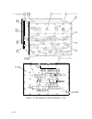
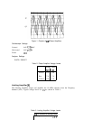
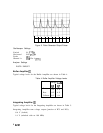
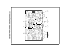

Figure 3. Pulse Generator Output Pulses
Oscilloscope Settings
Vertical 0.1
V/Div
Horizontal 0.05
ps/Div
Probe
1O:l
Channel A
U2B
Pin 4
(TPl)
Analyzer Settings
INSTR PRESET
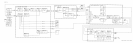
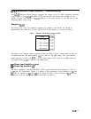
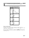
Buffer Amplifier
@
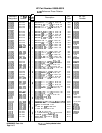
Typical voltage levels for the Buffer Amplifier are shown in Table 4.
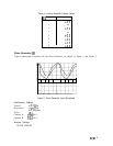
Integrating Amplifier
@
Typical voltage levels for the Integrating Amplifier are shown in Table 5.
Integrating Amplifier tune voltage output (junction of R75 and R51):
-8.6 V (locked)
-1.4 V (unlocked with no 100 MHz)
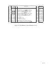
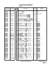
Table 4. Buffer Amplifier Voltage Levels
1
Voltage
Level:
Q3
Q7
Emitter
-4.6
-4.6
Base
-4.5
-4.5
Collector
-0.3 -9.4
s
6
A7Al