


Al
lA5
Al
IA5
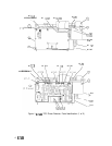
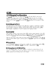
Sampler,
Circuit
Description
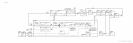
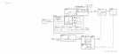
The
AllA
Sampler mixes the output of the
AllA
YTO (RF INPUT) with the Nth
harmonic of the output of the A7 M/N Reference Loop (M/N IN). The 20 to 30 MHz
difference signal (IF OUT) is output to the
AllA
YTO Phase Detector to be compared
with the 20 to 30 MHz
(20/30
IN) from the A10
20/30
Synthesizer for the purpose of phase
locking.
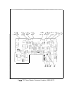
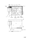
Sampler
Drive
Amplifier
@
The output of the A7 M/N Reference Loop (M/N IN) is applied to common-base amplifier
Q3. The output of Q3 is ac coupled to common-emitter amplifier QS. The output of
QS
is
passed through an impedance matching network which provides maximum drive power to
AllUl Sampler. Adjustments Cl and C2 optimize this impedance match.
Sampler
Al
1Ul
AllUl Sampler contains a step recovery diode (SRD)
circuit to create harmonics of the M/N
IN signal which are mixed with the low-level (-15
dBm)
RF INPUT signal from the
AllA
YTO (via the
AllAl
Coupler/Isolator/Amplifier and
AllA
Attenuator/6.2
GHz LPF).
When the YTO Loop is phase locked, the mixing product of the Nth harmonic of the M/N IN
signal and the RF INPUT signal is precisely equal to the
20/30
IN signal from the A10
20/30
Synthesizer.
IF
Preamplifier
@
The IF Preamplifier consists of common-source amplifier Q4, common-emitter amplifier
Q2,
and feedback divider
R20/R16.
0
Vera11
gain provided is approximately 14 dB.
Buffer
Amplifier
@
and
70
MHz
LPF
@
The AllUl Sampler output, after being amplified, is buffered by emitter-follower Q7 and
applied to a 70 MHz low-pass filter. This filtering is done to remove any unwanted mixing
products produced by the mixing action of the sampler.
AllA
1