


AlOA8
AlOA8
Phase
Lock
Loop
2
(PLL2)
Discriminator,
Circuit
Description
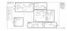
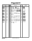
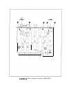
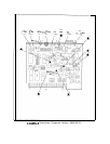
The AlOA8 PLL2 Discriminator combines the error voltage information from the AlOA6
PLL2 Phase Detector, the attenuated scan information (SCAN DAC IN) from the Al6 Scan
Generator, and the tuning information from the Al2 Front-Panel Interface (via the Instrument
Bus) to produce a tuning current to tune the oscillator in the AlOA5 PLL2 VCO.
Pulse
Generator
@
AlOA5 PLL2 VCO provides an ECL level
.15
to
.30
MHz input which is amplified by Q6
and Q7. At the beginning of a cycle, both inputs of gate U7D are low. When Q7 collector
goes high, U7D output goes low, saturating
Qll
and causing resonator L4, C15, Cl6 to ring
at 5.2 MHz. This damped oscillation appears at
Q9
collector, is clipped by
&lo,
and used to
drive counter U6. U6 is preset to a count of 6. When the count reaches 8, the (8) output of
U6 goes high. This is fed back to the other input of U7D, holding its output low after the
input from Q7 goes low. After 1.6
ps,
the count reaches 16, (8) goes low again,
U7D
output
goes high,
Qll
is turned off, resulting in the resonance being damped by R17. At the count of
16, U7C and U7B reset the counter to 5. Before the oscillation is fully damped, the counter
gets clocked to 6. U7A prevents a latch-up condition by clearing the counter in the event that
the output of U7D remains low for a long period of time.
-7
V
Reference
Supply
@
U13 biases reference diode
VRl
at 7.5
mA,
and provides a low impedance source at -7.0 V
dza%
Current
Source
@
The -7 V source, via R6 and Q3A, provides current which develops a stable 7 V drop across
R7 and Q3B. This acts as the reference for a 3.2 mA current source comprised of U4 and Q4.
This current flows to ground through Q5A when the (8)
output of U6 is low. If an input pulse
has triggered the pulse generator, the current is switched through
Q5B
for 1.6
ps.
Q5B’s
collector current goes through a low-pass filter to the summing point of the discriminator loop.
The average value of this current is directly proportional to the input frequency, being 1.5 mA
at 300 kHz. The current to frequency ratio is adjustable
*l%
by the phase lock input on
PI-28.
AiOA8
1