


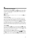

A5A2
Rotary Pulse Generator
@J
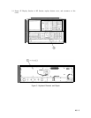
A5A2 Rotary Pulse Generator (RPG) is operated by turning the front-panel DATA knob
in either direction. The rate and direction of knob rotation are encoded in the number
and relative phase of output pulses on the
RPGl
and RPG2 lines. These two signals are
decoded on the Al2 Front Panel Interface, enabling the Al5 Controller to gradually change
appropriate instrument settings.
LINE Power Switch
@
When the LINE switch is in STANDBY, the LSBY
(Low=STANDBY)
line is grounded. If the
RF Section is connected to an ac power source, the
+22
V dc supply lights the STANDBY
LED, holds the
A23Kl
Fan Relay in the off state, and powers the heater circuit of the A22A2
10 MHz Quartz Crystal Oscillator; all other power supplies are turned off. When the LINE
switch is switched ON, the
A23Kl
Fan relay is released to the on state (switching on the fan)
and LSBY rises to about
+22
V dc (d
ue to the Fan Relay coil). This enables the
+20
V dc
supply on the Al7 Positive Regulator, which causes all the power supplies to turn on.
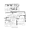
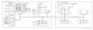
Front Panel Removal and Repair
With ac line cords removed, proceed as follows.
1. Remove interconnecting cables between instruments.
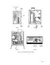
2. Position instrument on right side as shown in view A of Figure 1.
3. Remove feet
@
from rear of RF Section by removing screws
@
shown in view A of Figure
1.
4. Loosen bottom cover screw
@
and remove cover.
5. Loosen thumbscrews
@
and separate instruments by holding IF-Display Section in place
while pushing the RF Section at the front panel.
6. After separating instruments, slide RF Section away from IF Display Section far enough
to remove screws
@
holding front panel to frame. Refer to view B of Figure 1.
7. Remove screws
@
from other side of instrument. Refer to view C of Figure 1.
8. Pull front panel out of frame as shown in view D of Figure 1.
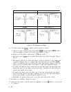
9. Disconnect cable
@
from connector
0.
Disconnect cable
@J
from connector
8.
Refer to
view D of Figure 1.
10. To replace INSTR CHECK and STANDBY LEDs proceed as follows.
a. Unsolder the wires from the LED leads and push on the leads with a soldering aid to
force the LED out of the socket and through the front panel.
b. Insert a new LED and resolder as shown in Figure 2.
c. Trim excess lead length.
2
AS