


+20
V
Regulator
@
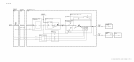
The
+20
V supply has as its reference a 6.2 V zener diode VR2 biased from the output of
the j-20 V supply,
@
on the schematic. The
+20
V output is divided down by R9, R50,
and
RlO to 6.2 V. This voltage is compared with the
t6.2
V reference voltage by amplifier
Ul.
This amplifier sinks current from the current source
Ql
so that the voltage at the base of the
series-pass transistor A23Q23 (on A23 Motherboard) is such that the output of the supply is
at
+20
V.
A simple form of
foldback
current limiting is provided by the current sensing resistor R3, R4,
R5, CR4, and Q3. 0
vervoltage protection is provided by the
+20
V crowbar
@
consisting of
VR3 and
CRl.
DS2 is an LED which indicates the presence of an output voltage. Fuse F2
provides further protection for the supply.
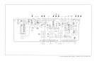
+20
V
Switched
Supply
@
The
+20
V switched supply provides power to the oscillator circuits of the A22 10 MHz
Frequency Standard. If the Reference Disable line HSTD is low,
QlO
is off, and
Q9
is off, so
no power is supplied to the internal 10 MHz oscillator. When HSTD goes high, both
Q9
and
QlO
turn on, and i-20 V is supplied to the internal 10 MHz oscillator.
+12
V
Regulator
@
The i-12 V supply is a 12 V floating regulator with its reference terminal biased at 11 V by
R24 and VR8. This supply is enabled by the presence of the -5.2 V supply, which causes
QS
to turn off, allowing the zener diode VR8 to be biased by the current flowing from the output
of the supply through R24. LED DS4 provides a visible indication of an output voltage.
Overvoltage protection is provided by the
-l-12
V crowbar
0.
The regulator itself is internally
protected, but further protection is provided by CR3 and
Fl.
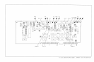
+5.2
V
Regulator
@
The operation of this supply is similar to that of the
+20
V supply. Its reference is from the
voltage divider R36 and R49 from the i-20 V supply. This voltage is compared with the
divided down output voltage by U2, which drives the Darlington-connected transistors Q6
and Q4 and the series-pass transistor A23Q4 on the A23 Motherboard.
Foldback
current
limit is provided by R27-29, R31, R32, and Q5. The output crowbar
@
provides overvoltage
protection. Further protection is provided by F3.
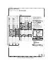
Power
Up/Down
Detector
@
A power-up indication HPUP is provided to allow the instrument to turn on and off in an
orderly manner. The HPUP line goes high when all of the following conditions are met:
1. The rectified dc voltage of the
+5.2
V Unreg supply is above 8.6 V (provides an indication
that the Line Voltage is present).
2. The
t5.2
V output is higher than
t4.9
V.
3. The front-panel shutdown and thermal shutdown circuits allow the instrument to be turned
on.
If both the front-panel shutdown and thermal shutdown transistors
Qll
and Q12 are
off, CR11 is reverse biased. If the output of the i-5.2 V supply is greater than i-4.9 V,
2 Al7