


Analog
Troubleshooting
Phase Lock Loops Principles of Operation
General Description
The fundamental RF signal input to the A6 RF Module (2 to 6.2 GHz) is generated by the
AllA
YTO
(YIG-T
uned Oscillator). This signal is phase-locked, through other phase-lock
loops, to the A22 10 MHz Standard (internal crystal oscillator). The YTO Loop pretunes and
locks the YTO signal to the output of the M/N Loop (part of A7) and the A10
20/30
Loop.
The M/N and
20/30
Loops serve two basic functions.
First, they phase-lock the YTO Loop
to the 10 MHz Standard through the Reference Loop (part of A7). They also provide the
stepped tuning of the YTO output signal. The M/N Loop provides the larger steps (2000 to
6199 MHz in 10 MHz steps) while the
20/30
Loop provides the smaller (1 MHz to 1 Hz) steps.
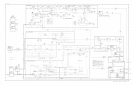
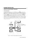
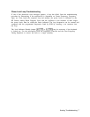
All phase lock loops are referenced, either directly or indirectly, to the A22 10 MHz Standard.
Figure 1. shows the relationship between the various loops as well as defining the assemblies
associated with the loops.
4
3.3
GHz
t
HETERODYNE
100 MHz
1
lf:%fo;Hz
,
I
REFERENCE
10 MHz and 100 MHz
LOOP
PLLl
&
PLL3
(A7Al.A7AZ)
)
(AlOAl-AlOA4)
20 MHz
165-
10 MHz
10 MHz
STANDARD
(A2’J)
10 MHz
PLL2
b
(AIOAS-~10~8)
fYTO
2.3-6.1
(200N-1
GHZ
OM-
f20/30)
Figure 1. Phase Lock Loops (Synthesizer), Block Diagram
Analog Troubleshooting 1