


RF Section Internal Fuse Replacement
Note
d
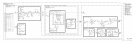
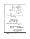
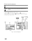
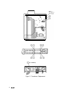
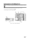
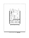
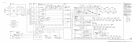
For location of hardware and cables referred to in this procedure, see Figure 1.
Warning
Remove ac line cord from both instruments before proceeding with this
9
procedure.
1. Position instrument upside-down as shown in view A.
2. Remove feet
@
from rear of RF Section by removing screws
@
show in view A.
3. Remove bottom cover by loosening screw
@
and pulling cover toward rear of instrument.
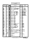
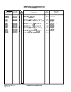
4. Location of fuses is shown in view B.
Fl
+22V
1A
L ,
,
A8
RECTIFIER
Fl
+12V
1A
Fl
-5.2V
2.5A
F2
+2OV
3A
F2 -40V
1.5A
F3
+5.2V
6A
F3 -lOV 5A
--
Al7 Al8
POS REG NEG REG
VIEW A
VIEW B
Figure 1. Internal Fuse Replacement
2
A8/A9