


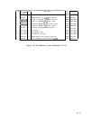
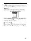
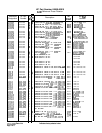

Table 3. Limiting Amplifier Voltage Levels
LJl
Pin Number dc Voltage Level
1
+5.0
2
0.0
3
+0.5
4
0.0
5
+2.3
6
+2.3
7
+1.6
8
I
t5.0
Pulse Generator
@
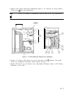
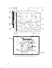
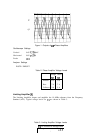
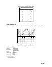
Typical input/output waveforms for the Pulse Generator are shown in Figure 2 and Figure 3.
Figure 2. Pulse Generator Input Waveforms
Oscilloscope Settings
Vertical 0.1
V/Div
Horizontal 0.2
ps/Div
X10 Magnifier
Probes
1O:l
Channel A U2B Pin 5
Channel B
U2A Pin 2
Analyzer Settings
INSTR PRESET
A7A7
5