


AIOAG
AlOA6
Phase
Lock
Loop
2
(PLL2)
Phase
Detector,
Circuit
Description
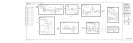
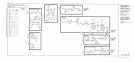
The purpose of the AlOA6 PLL2 Phase Detector is to compare the output of the AlOA5
PLL2 VCO (after division by the AlOA7 PLL2 Divider) to the 500 kHz Reference from the
A7Al
Reference Phase Detector. The phase difference is converted to an error voltage used to
correct the PLL2 VCO frequency.
Phase-Frequency Detector
@
The phase-frequency detector responds to the phase difference between the 500 kHz reference
input and the divided input from the AlOA7 PLL2 Divider. Assuming both flip-flops U6A
and
U6B
have been cleared,
Q9
is on and
QlO
is off.
Q9
supplies about 3
mA
current which
is sunk by current source
QS
resulting in approximately zero current flow through the 50
kHz low-pass filter to U3. On AlOA6 PLL2 Phase Detector, HP part number 85660-60276,
transistor
Qll
is added as an active
pulldown
to reduce glitches that could cause momentary
false unlocks.
A pulse from the PLL2 Divider on Pl-19 clocks the Q output of U6A high, turning
Q9
off. A
subsequent reference pulse on Pl-20 clocks the Q output of
U6B
high, which will immediately
reset both flip- flops through U7A. Thus the effect of a pulse at Pl-19 leading one at Pl-20 is
to momentarily reduce the output current. Therefore, if the divided output leads the reference
in phase, the current decreases. Similarly, if the reference phase leads, the current increases
because
QlO
is connected to the Q output of U6B.
If the two inputs have different frequencies, the pulse relationships become complicated, but
the net effect is positive output current if the reference frequency is high.
U3 serves as an amplifier to provide the high currents necessary to rapidly charge the
integrating capacitor C7 in the following stage. VR2 and VR3 serve as clamps, limiting the
output swing to f5.8 V.
Unlock
Indicator
0%~
When the phase lock loop is in a steady state condition, the voltage at
TPl
is zero. If
unlocked, the voltage will be non-zero except for transients passing through zero. When
the voltage
TPl
exceeds
f0.7
V, either
Ql
or
Q2
is turned on, discharging Cl5 or Cl4
respectively and tripping comparator
Ul.
When
TPl
voltage settles to less than f0.7 V, Cl4
and Cl5 must recharge before the comparator is reset. This takes 5 ms. The comparator
output is TTL high for an unlock condition and remains there for 5 ms after a lock condition
is established.
AlOA6
1