


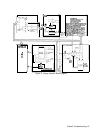
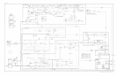

Reference Loop (Part of A7)
The Reference Loop is phase-locked to the A22 10 MHz Standard and its phase-locked
outputs (10, 20, 100, and 400 MHz) are used as references for the
20/30
Loop, the M/N
Loop, and the Heterodyne Loop (part of A6). The 10 MHz signal is also used as an auxiliary
rear-panel output.
The A7A2 100 MHz VCXO (Voltage-Controlled Crystal Oscillator) is the heart of this loop.
The 100 MHz output signal is 1) routed to the A6A9 Phase Lock assembly to be used as a
reference for the Heterodyne Loop and as the front-panel CAL OUTPUT signal, 2) routed
to the AlOA3 PLL3 Up Converter to be used as a reference for that phase-lock loop, 3)
multiplied by four to produce the reference signal for the M/N Loop (A7A3 M/N Phase
Detector), and 4) divided by five to produce a 20 MHz reference signal also used by the
M/
N Loop. The 20 MHz signal is divided by two to produce a 10 MHz signal which is used
as a reference for the
PLLl
and PLL2 phase-lock loops in the
20/30
Loop and also as the
rear-panel auxiliary output. The 10 MHz signal is also phase compared to the output of the
A22 10 MHz Standard. The resulting error signal is used to tune the 100 MHz VCXO to
phase-lock the Reference Loop.
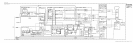
M/N Loop (Part of A7)
The frequency output of the M/N Loop is dependent on the front-panel Start
Frequency/Center Frequency and in part, controls the YTO output frequency. This signal is
disabled during sweeps when the frequency span is greater than 5 MHz (fundamental mixing).
An encoded equivalent of the front-panel frequency’s most significant digits are input to the
M/N Loop as M and N numbers. The ratio of the M and N numbers determines the M/N
OUT
(fM,N)
frequency and are chosen such that the Nth harmonic (same as the divider
number) of
fM/N
tunes in exactly 10 MHz increments as M is changed. There is one 10 MHz
step for each valid
fM/N
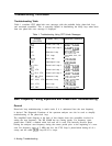
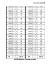
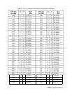
frequency (M/N ratio) and Nth harmonic (N number). Refer to Table
2 for a complete list of M and N numbers and resulting
fM/N
frequencies. This 10 MHz step
complements the
20/30
Loop whose tuning range is 10 MHz and step size is 1 Hz. Together,
the M/N loop, YTO pretuning, and
20/30
Loop are able to tune the
AllA
YTO from
2000.000 000 to 6199.999 999 MHz in 1 Hz steps.
YTO Loop (All)
Whenever a change is made to the Start Frequency/Center Frequency (from the front panel
or remote controller), the YTO is pretuned near the desired new frequency. This is done
by encoded information being sent from the Al2 Front-Panel Interface to the A19 DAC
(Digital-to-Analog C
onverter) which generates and routes an analog voltage to the A20 Main
Coil Driver. The Main Coil Driver, in turn, generates a tuning current to tune the YTO. This
places the YTO frequency 20 to 30 MHz below the Nth harmonic of the M/N Loop output
(fM,N).
For frequency spans greater than 5 MHz, the YTO frequency is locked at the start
of each sweep with the M/N loop and the
20/30
loop to a 1 Hz resolution. The YTO signal
(fYTO)
and the M/N Loop output signal
(fM,N)
are mixed in the
AllA
Sampler (harmonic
mixer) to produce the YTO IF
(f
YT~JIF)
signal. This 20 to 30 MHz signal is phase compared
to the
20/30
Loop output signal
(f2e,ao)
in the
AllA
YTO Phase Detector producing a dc
error voltage. It should be noted that
fYTC)IF
and
fze/se
are equal when the YTO Loop is
phase-locked. This error voltage is stored in a capacitor, the loop (YTO) opened, and a sweep
taken. The loop is relocked at the start of each sweep. If the frequency span is less than 5
MHz, the YTO Loop is always locked and is forced to sweep by following the swept oscillator
2 Analog Troubleshooting