


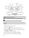
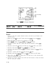
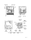
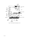
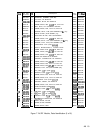

30. Reconnect all wire harness connectors to A6A5 ACLU and A6A4 2nd Converter as
follows.
n A6A4 2nd Converter
green
(5)
Wire
to
IE
white/brown (91) wire to
V,
white/black (90) wire to SW
n A6A5 ACLU
gray (8) wire to BIAS
white/red (92)
wires to
+5
V dc (three pins)
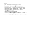
31. Reconnect wire harness to motherboard.
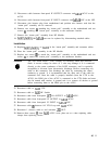
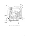
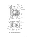
32. Replace A6A9 assembly and A6A10,
A6Al1,
and A6A12 PC boards.
33. Replace PC board cover and install six screws
0.
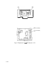
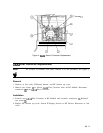
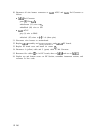
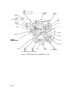
34. Reconnect 4 (yellow) cable and 5 (green) cable to 2nd Converter.
35. Reconnect five cables
0
to A6 PC boards; three to A6A9 and two to A6A12.
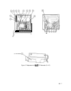
36. Replace top and bottom covers on RF Section, recombine instrument sections, and
reconnect ac line cords.
12 A6