


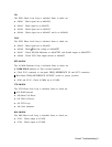
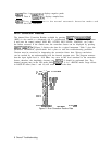
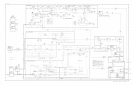

Sweep System Block Diagram Description
The HP 8566B Spectrum Analyzer sweep system consists of the following modes:
Continuous Sweep; Free Run Trigger
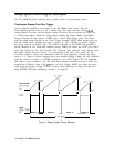
Several different assemblies are involved in the HP 8566B sweep system. The Al6
Scan Generator generates the 0 to 10 V sweep ramp. The ramp converter on the
A3A8
Analog-Digital Converter and the Digital Storage Processor Section digitize this ramp into
a
10-bit
sweep address. When the sweep address reaches the marker address, the Digital
Storage Processor Section outputs a RSHS (Low = Reset High Sweep) pulse. This signal
resets the High Sweep flip-flop on the
A3Al
Trigger assembly. HSWP (High Sweep) goes low
and the current source charging the sweep capacitor on Al6 is shunted to ground, stopping
the sweep ramp at its present value. The negative transition on the HSWP line generates a
Service Request on Al2 Front-Panel Interface forcing LSRQ low which sets LSTP (Low Stop)
high. This “wakes up” the Al5 Controller. The Controller then reads the sweep address from
the Digital Storage Processor Section. If it corresponds to the end of the sweep, the Al5
Controller outputs a sweep reset command to the Al6 Scan Generator, resetting the sweep
ramp to 0 V. After all Service Requests have been handled (LSRQ is high), the Al5 Controller
starts the sweep by issuing a set HSWP command to the
A3Al
Trigger. The Al5 Controller
then issues a stop command to the Al2 Front-Panel Interface assembly that forces LSTP low,
stopping the Controller. After a 500
ps delay on
A3Al
Trigger, HSWP goes high, the sweep
ramp starts, the Digital Storage Processor Section starts digitizing the ramp, and the front
panel SWEEP LED lights indicating a sweep is in progress.
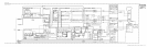
+1.9oov
+1
,700v
SCAN RAMP
(A16TP3)
ov
I
I I
I I
I I
I
I
I
I
I
I
I
I
+5v
HSWP
(A3AlTP4)
ov
BAND B
-
BAND C
1
BAND D
r
BAND E
t
2-22 GHz
I
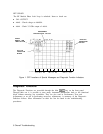
Figure 3. Sweep System Timing Example
10
Overall Troubleshooting