


Notes
1. The suffix or subscript 0 denotes the least significant bit (LSB) of a data or address word.
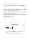
2. Letters may be used to identify a line or logic element without indicating a specific logic
function. For example:
---A
---B
-C
MUX
O-
7---
l A
O-
l+---
l B
0
l---
l c
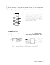
Triple Z-Channel Multiplexer
Letters are used to relate control
inputs to logic elements.
The
numerals 0 and 1 indicate O-state
and l-state,
respectively, and
relate the position of a “switch”
to the logic state of the corres-
ponding control line.
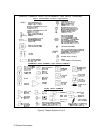
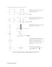
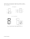
DEPENDENCY (G and F)
The dependency of
inputs or outputs on an input
is
indicated with
gate symbols or the G line label.
Gate symbols are often used when
the dependency exists between inputs. Two examples are:
1
Two inputs
ANDed
to
produce a
reset
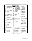
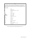
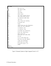
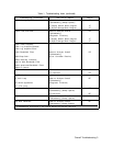
Figure 6. Schematic Symbols for Digital Integrated Circuits (5 of 7)
General Information 17