


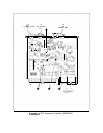

However, the Fractional Divide circuit can set the integer divider to a “hold” state every
N pulses, causing it to “swallow” a pulse and effectively divide by
N+l
for a cycle. In this
example, the Fractional Divide circuit selectively causes the integer divider to “swallow” a
pulse in 57 out of every 100 divide cycles. The integer divider thus divides by 8 for 43 out of
every 100 cycles and by 9 for 57 out of every 100 cycles, averaging out to the desired value of
8.57. Filtering in the phase-lock loop causes the
PLLl
VCO to lock steadily to this average
value.
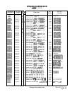
The fractional divide number is programmed into
Ul
and U2 as two 4-bit BCD bytes.
Ul
and U2 are TTL decade rate multipliers connected in cascade. The input comes from the
integer divide counter U12 via U4B and the ECL to TTL translator consisting of U3B and
Ql.
For every 100 clock pulses into
Ul
and U2, there is output from U3A equal to 100 times
the fractional part of the divide number
Nl.
For example, if
Nl
= 8.57, then 57 pulses occur
at U3A output for every 100 pulses into
Ul/U2.
U3A translates the TTL outputs of
Ul
and
U2 to ECL, which then are latched by U15B, synchronized by U14A, and fed back to U12 to
control pulse “swallowing.”
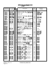
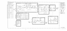
Phase/Frequency Detector
@
The phase/frequency detector compares the divider output with a 5 MHz reference frequency.
When the two inputs are in phase, the outputs are ECL high, approximately
+4
V, with very
narrow pulses at a 5 MHz rate. When the inputs are the same frequency but different in
phase, one output line is a pulse with a width corresponding to the phase difference; the other
output is high with very narrow pulses. For a difference in input frequencies, the outputs
are pulses of varying widths, but with different average dc voltage levels. The sign of this dc
voltage is set by which frequency is higher and the magnitude is determined by the amount of
frequency difference.
Reference
Divide
by
2
@
U7C is an input buffer amplifier which generates the proper level for ECL (approximately
+3
V low and
+4
V high). U15A divides the 10 MHz input by 2 and applies this 5 MHz to
the phase/frequency detector.
Phase
Lock
Indicator
@
The input to the phase lock indicator is the wired OR Q outputs of the phase/frequency
detector. This input is ECL low (approximately 3 V) when the loop is locked; in this
condition, the dc voltage at the base of Q3 is lower than that at the base of Q2 so Q3 is on
and
Q2
is off. If the loop unlocks, the input to the phase lock indicator consists of varying
width pulses, the average dc value of which is about half way between a logic low and high.
The voltage divider consisting of R35 and R15 causes the voltage at
Q2
base to be lower than
that at Q3 base, so Q2 turns on indicating an unlock condition.
If
PLLl
unlocks, LED
DSl
will turn off, and the CRT message
PLl
UNLOCK will appear.
However, the CRT message PLI UNLOCK will also appear if PLL3 unlocks, as indicated when
AlOA4DSl
turns off. In spans above n x 5 MHz and spans of n x 100 kHz and below, PLL3
functions to shift the output of PLL2 up in frequency by 160 MHz for further division by
PLLl.
(n is the harmonic mixing number.) The two loops PLL3 and
PLLl
always operate
in conjunction; if PLL3 unlocks, then the output of
PLLl
is incorrect whether or not
PLLl
unlocks. The single CRT message
PLl
UNLOCK is used to indicate an unlock in either
PLLl
or
PLL3.
2
AIQA2