


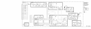
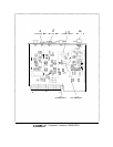

Phase/Frequency Detector
@
U6B and U6C are ECL buffer amplifiers which have the proper output amplitude and dc level
(approximately
+3
V low and
+4
V high) to drive the phase/frequency detector. When the
phase detector inputs have the same phase, the outputs are ECL high with narrow negative
coincident pulses. If there is a phase offset, the pulse widens on one of the outputs depending
on which signal is leading in phase. When the input frequencies are different, the outputs
consist of varying width pulses; the dc or average value of the outputs are different depending
on which frequency is higher and by how much.
Phase
Lock
Indicator
@
The phase lock indicator senses the outputs of the phase detector which are ECL logic high
when the loop is locked. When the loop is not locked, the average phase detector output level
drops to half way between a logic low and logic high.
UlA
switches when this occurs and
causes
DSl
to go out and the phase lock output
HULl
to go to TTL high.
If PLL3 unlocks, LED
DSl
will turn off, and the CRT message
PLl
UNLOCK will appear.
However, the CRT message
PLl
UNLOCK will also appear if
PLLl
unlocks, as indicated when
AlOA2DSl
turns off. In spans above n x 5 MHz and spans of n x 100 kHz and below, PLL3
functions to shift the output of PLL2 up in frequency by 160 MHz for further division by
PLLl.
The two loops PLL3 and
PLLl
always operate in conjunction; if PLL3 unlocks, then
the output of
PLLl
is incorrect whether or not
PLLl
unlocks. The single CRT message
PLl
UNLOCK is used to indicate an unlock in either
PLLl
or PLLS.