


100K
--
IOK
--
RR
IK------
---- ---
L
I
I I
I
,
I
I
I
I
50”
60°
70”
80°
90’
loo0
1
loo
TEMP
“C
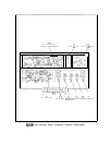
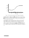
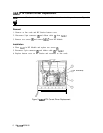
Figure 1. YTX Thermal Sensor Resistance versus Temperature Characteristics
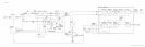
Op-amp
Ul,
with R2, R3, R4,
Ql,
and Q7 f
arms
an amplifier with a gain of about 127. In
addition, R2 and R3 set a reference voltage at the negative input of the amplifier. Darlington
Ql
and Q7 is able to provide the large currents required to heat the heater resistor to 75°C.
VR2 and R5 offset the op-amp output voltage to be within range of the output stage (0 to
-40 V). CR1 protects the op-amp input.
The circuit operates as follows: If the heater ring is cool (such as at turn-on), the divider
formed by
Rl
and the sensor (described above) outputs a voltage that is less than the
reference at the minus input to the amplifier. This causes the amplifier output to swing
negative, thus drawing more current through the heater resistor, heating up the sensor,
causing it to increase its resistance. This raises the voltage at the
Rl/sensor
divider output
until it exactly equals that of the reference divider
R2/R3.
In general, small temperature
errors are manifested as a small voltage between pins 2 and 3 of the op-amp (its input). This
error is amplified and applied to the heater resistor with the appropriate sign to eliminate the
error.
2
A6A7/A6A5/A6A8