


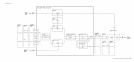

Voltage-Controlled Oscillator
6~
The M/N voltage-controlled oscillator (VCO)
consists of a resonator
A7A4AlAl
and
Q2
with
its associated circuitry. The oscillation frequency is determined by the bias on the varactors
CR1 and CR2 which tunes the cavity resonator. Coarse tuning is provided by Cl, while
C5 is used to vary the output coupling to the cavity thereby varying the output power.
The impedance looking into the emitter of Q2 has a negative real part which provides the
conditions necessary for oscillation to occur.
Buffer Amplifier
@
Ql
is a common-emitter buffer amplifier which provides at least 0
dBm
output over the 355 to
395 MHz range of the VCO.
LO Amplifier
@
QS
and Q7 form a buffer amplifier to assure that there is approximately 0
dBm
to drive the
ECL divide-by-2 IC (U2 in block
0).
R24 and R25 set the proper dc level to drive U2.
M/N Output Amplifier
@
Q3 and Q4 provide buffering between the ECL divider
U2
and the output.
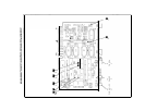
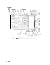
A7A4 M/N Output, Troubleshooting
The VCO tune voltage from the A7A3 M/N Phase Detector is amplified and applied to the
Voltage-Controlled Oscillator (VCO) by the loop amplifier. The VCO output is amplified,
divided by two, and applied to the
AllA
Sampler for phase locking the
AllA
YIG-Tuned
Oscillator (YTO)
in 10 MHz increments. A portion of the VCO output provides feedback to
the A7A3 Phase Detector for phase locking of the M/N Loop.
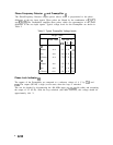
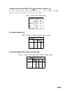
Spectrum analyzer control settings for A7A4 troubleshooting:
(2-22)
(SHIFT)
(MKRJREF
LVL) (KSR)
(SHIFT)
(BW)
(KSF)
(CENTERFREQUENCY)
. . . . . . . .
[FREQUENCY SPAN) . . . . . . . . . .
.
.
.
.
.
.
.
.
.
.
.
.
.
.
.
.
.
.
.
.
.
.
.
.
.
.
.
.
.
.
.
.
.
.
.
.
.
.
.
3.77
.
.
.
.
.
.
.
.
.
.
.
.
.
.
.
.
.
.
.
.
.
.
.
.
.
.
.
.
.
.
.
.
.
.
.
.
.
.
.
.
.
.
.
GHz
0 Hz
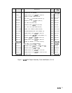
Loop Amplifier
@
The tune voltage from the Loop Amplifier can be measured at
TPl,
located on the cover of
the A7A4. The dc voltage at
TPl,
with the front panel settings indicated above, shoud be
-14.2 V. If an unlocked condition exists, the voltage is approximately -0.5 V or -37.5 V.
If the level is -0.5 V, the probable cause is no VCO output to the A7A3 Phase Detector.
A level of -37.5 V indicates that the 20 MHz reference to the A7A3 Phase Detector is not
present.
2
A7A4