


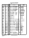
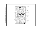
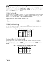
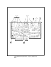

A7A2 100 MHz VCXO, Troubleshooting
The 100 MHz VCXO supplies all of the fixed reference frequencies for the HP 8566B. Separate
100 MHz outputs are routed to the A6A9, AlOA4, and
A7Al
assemblies. A 400 MHz signal is
applied to the A7A3 assembly. The
A7Al
assembly divides the 100 MHz input to provide 10
MHz and 20 MHz references.
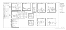
100 MHz Oscillator
@
The tune voltage at
A7A2TPl
is nominally -8 V. If an unlocked condition exists, this voltage
is either -23 V or -1.3 V. If the level is -23 V, check the 10 MHz reference to
A7Al.
If the
level is -1.3 V, check the outputs of the 100 MHz Buffer/Amplifier.
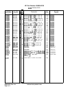
Typical voltage levels for the oscillator transistor Q5 are:
Emitter ..........................................................
-12.8V
Base .............................................................
-11.9V
Collector
..........................................................
..O.O V
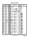
100 MHz Buffer/Amplifier
@I
All 100 MHz output levels should be approximately 0
dBm.
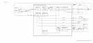
Typical voltage levels for each
transistor are as shown in Table 1.
Q6
Q7
Qll
Emitter
4.0
3.9
3.9
Base 4.7 4.7 4.6
Collector
9.3
9.4
9.4
Table 1. 100 MHz Buffer/Amplifier Voltage Levels
Quadrupler
@
and 400 MHz Amplifier
@I
Typical voltage levels for the Quadrupler and 400 MHz Amplifier are as shown in Table 2.
The 400 MHz Amplifier output at
A7A2Jl
(96 cable)
is approximately -10
dBm
when the
A7A2 100 MHz board assembly is in the casting.
Table 2. Quadrupler and 400 MHz Amplifier Voltage Levels
Q3 Q4
Ql
Q3
Emitter -4.6 -5.1 -6.6 -6.6
Base
-5.9 -5.9 -5.9 -5.9
Collector
0.0
0.0
0.0 0.0
2
A7A2