


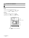

A6A7 YIG-Tuned Mixer (YTX) Current Driver, Circuit Description
The YTX Current Driver has three functions:
1. Provides the output stage for the A6A8 YTX coil.
2. Provides filter circuitry for the YTX.
3. Provides control circuitry for the YTX heater.
YTX Drive Output
@
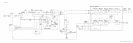
The YTX drive output consists of Q5,
QS,
R14 to R17, VR4, and CR3. Q5 and Q6 form a
darlington transistor driven by the A6A12 YTX Driver. R14 to R17 are four 1000 ten-watt
resistors connected in parallel to form a 25R resistor which is used to sense the current in
the YTX coil. This sense signal is fed back to the YTX Driver. Four resistors are used for
power handling capability and temperature stability. VR4 and CR3 limit the flyback voltage
produced across the YTX coil during scan reset and prevent breakdown of Q5 and Q6.
Filter Capacitor Drive
@
When the spectrum analyzer is set to narrow spans and narrow resolution bandwidth, hum
and noise in the YTX drive circuitry which FMs the YTX can introduce phase noise and
line frequency sidebands onto a displayed signal. To prevent this occurrence, a large filter
capacitor, A6A7C1, is connected across the YTX coil by switch
QS
whenever the resolution
bandwidth is 100 Hz or less.
QS
is controlled from
A6All
Slope Generator through Q2, Q3, and Q4. When the resolution
bandwidth is 100 Hz or less, the filter capacitor is connected before the start of a scan and
disconnected at the end of a scan so that the scan reset and hysteresis correction can be
performed.
YTX Heater Control
@
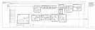
The YTX heater control is a feedback circuit designed to maintain the center support of the
YTX at a constant 75”C, as the ambient temperature ranges from 0“ to 55°C. The green
LED,
DSl,
indicates that current is flowing properly in the heater. Red LED, DS2, indicates
the circuit is saturated, putting maximum power into the heater.
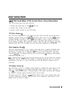
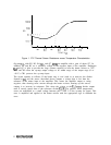
The heater ring of the YTX has a
4500
thin-film heater resistor, and a thermal sensor with
a positive temperature coefficient. The resistance versus temperature characteristics of the
thermal sensor are shown in Figure 1.
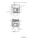
A6A7/A6Aii/A6A8
1