


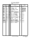

For example:
If M = 26,
N = 20,
and VCO Frequency = 187.0 MHz,
then M/N output frequency = N (VCO) = 20 x 187.0 = 3,740 MHz.
If M is changed to 25,
then the VCO frequency changes to 187.5 MHz,
and the M/N output frequency changes to 3,750 MHz (20 x 187.5).
Result
=
10 MHz change for M divider change of 1.
An incorrect M or N number, due to the main controller or a bad latch on A7A3, can be
easily detected. The frequency diagnostic
(SHIFT)
MKR+
REF
LVL
gives the M and N numbers
and the M/N output frequency (VCO divided by two) for the start frequency selected. A
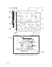
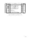
frequency counter attached to A7A4J2 indicates the actual frequency output. Table 2, “M
and N Numbers and Resulting Frequencies,”
of the RF Section Analog Troubleshooting tab,
lists all possible M/N output frequencies. By locating the M/N frequency measured by the
counter, the M and N numbers required to produce this frequency are obtained. The M and
N numbers can then be compared to those shown in the frequency diagnostic. The latch
and divider for the number in error can then be located using the troubleshooting procedure
outline for A7A3.
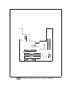
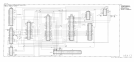
A7 M/N Reference Replacement
Note
I
w
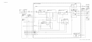
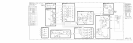
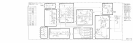
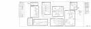
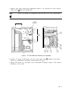
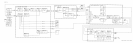
For location of hardware and cables referred to in this procedure, see Figure 1.
Removal
1. Remove ac line cords, IF-Display Section, and RF Section top and bottom covers.
2. Remove the following cables from A7 M/N Reference:
80 (gray/black) cable
(A7AlJ1,
STD IN)
0
86 (gray/blue)
cable
(A7AlJR,
10 MHz OUT)
@
9 (white) cable
(A7AlJ5,
10 MHz OUT)
@
85 (gray/green) cable
(A7A2J4,
100 MHz OUT)
@
8 (gray) cable
(A7A2J3,
100 MHz OUT)
@
93 (white/orange) cable
(A7A4J2,
M/N OUT)
@
6 (blue) cable
(A7AlJ6,
10 MHz OUT)
0
2 A7