


A6A8
YTX Replacement
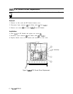
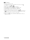
16. Reconnect coaxial cables to YTX.
17. Place A6A7 YTX Current Driver in RF Module and secure with two screws
0.
18. Reconnect 5-pin connector
@
to A6A7.
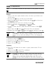
19. Replace ribbon cable
@
between A6A7 and motherboard.
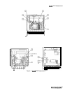
20. Replace A6A9 assembly and A6A10,
A6Al1,
and A6A12 PC boards.
21. Reconnect 4 (yellow) cable and 5 (green) cable to 2nd Converter.
22. Replace RF Module PC board cover and secure with six screws
0.
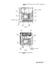
23. Reconnect five cables to RF Module PC boards; three to A6A9 Phase Lock and two to
A6A12 YTX Driver. Cables are color-coded and color codes are labeled on PC board
cover.
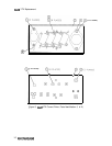
24. Reconnect cable
@)
between All YTO Loop and RF Module.
25. Replace top and bottom covers on RF Section, recombine instrument sections, and
reconnect ac line cords.
8
A6A7/A6AS/A6A8