


Note
The 100 MHz VCXO Tune Voltage can be measured at
A7A2TPl.
However,
the voltage levels will be slightly lower than those listed above.
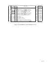
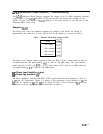
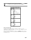
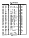
Table 5.
Integrating Amplifier Voltage Levels
lhnsistors
de Voltage Levels
24A
Pin 1
+0.18
Pin 2
+9.8
0.0
(locked)
Pin 3
0.0
(no 10 MHz)
Ref.
+O.l (no 100 MHz) VCXO
?4B
Pin 4
+0.18
Pin 5 +9.8
Pin 6 +o.o
25
Emitter
+10.3
Base
+9.8
Collector Gnd
26
Emitter
+10.3
Base
+9.8
Collector
-6.6
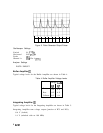
Phase Lock Detector
@I
The output of the Lock Indicator Sampler is compared to a reference of -0.4 V by
comparator U5. The output of U5 is high for any unlocked condition.
VRl
limits the output
voltage (HULR) to approximately 4.64 V.
This can be checked by disconnecting the 10 MHz input at
A7AlJl
(gray/white cable) and
measuring the output of U5. With the loop unlocked (10 MHz removed), this output should
be approximately 4.64 V.
A7A1
7