


Al5
Controller,
Troubleshooting
Troubleshooting the Al5 Controller is divided into two levels:
Level 1 is Self Test which uses the built-in diagnostics of the spectrum analyzer to isolate
the failure. No external test equipment is required.
Level 2 is Manual Tests which require the use of general troubleshooting equipment such as
a digital voltmeter and oscilloscope. This level is required when the Self Test can’t isolate
the failure.
Level
1
Self
Test
The Self Test is run on power-up and after pushing the [INSTRUMENT PRESET) key. Two
front panel
LEDs,
INSTR CHECK I and II, give an indication of Self Test results (without
removing any covers from the instrument). There are also 15 LEDs on the Al5 Controller
(DSl
through DS15) that will help isolate a problem.
Front
Panel
INSTR
CHECK
I
and
II
LEDs
The two red INSTR CHECK LEDs are forced on whenever the instrument is turned on or
the (INSTRUMENT PRESET) key is pushed. The main processor then performs a check of itself, a
checksum verification of all ROMs on the Al5 Controller, a partial check of the Instrument
Bus (50-wire bus), and a read/write check of the
RAMS
and A3A4 Memory in the IF-Display
Section.
If all the checks pass, both INSTR CHECK LEDs are turned off. If the check fails, one or
both INSTR CHECK
LEDs
remain on.
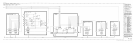
a. Both INSTR CHECK LEDs on indicates a problem on the Al5 Controller. First remove
the Al5 Controller and make sure that the 50-wire ribbon cable and HP-IB ribbon cable
are pressed all the way onto
A15Jl
and A15J2 connectors. Reinstall the Al5 Controller. If
both front panel INSTR CHECK LEDs still remain on when the instrument is turned on,
follow procedure under Al5 Controller Self Test.
b. Left LED (INSTR CHECK I)
on indicates a failure occurred when checking Digital Storage
Memory (A3A4). First check to ensure that a LINE power cord is connected to the
IF-Display Section. Also check to se that the rear-panel Analyzer Bus Interconnect Cable,
W31, is properly connected. If INSTR CHECK I still remains on when the instrument is
turned on, troubleshoot the A3 Digital Storage in the IF-Display Section.
c. Right LED (INSTR CHECK II)
on indicates a failure occurred during the partial check of
the Instrument Bus.
Note
The partial interface check reads the key column lines
(KC0
through
KC7) from the Al and A5 front panels. If any front panel key is shorted
or stuck closed, INSTR CHECK II LED should remain on after the Self
Test is completed. This part of the Self Test can easily be verified by
pushing any key, except
ILCL),
and holding the key in while pushing the
[INSTRUMENT PRESET) key. If the I/O interface check routine is working, INSTR
CHECK II LED will stay on.
d. Suspected Digital Failure but no INSTR CHECK LEDs on may indicate a RAM or I/O
bus failure which is not checked in the normal Self Test or “POP” (Power On Preset). If
4 Al5