


Q
OUT
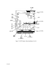
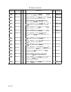
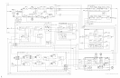
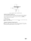
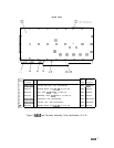
Figure 1. Step Gain Amplifier, Simplified Schematic
Amplitude Calibration Attenuator
@
Q2 is an emitter follower buffer driving a second pin diode attenuator, CR11 to CR14. The
current through CR11 and CR12 is determined by the front-panel control A6R1, AMPTD
CAL. The current through CR13 and CR14 is fixed by R27. This circuit provides for
amplitude calibration of the instrument.
21.4 MHz Output
@
Qll
and Q12 form the output stage for the Last Converter.
Qll
is an emitter follower driving
a common emitter amplifier Q12.
Temperature Compensation Voltage Source
@
Ql
provides a voltage to set the current in CR8 to CR10 and CR15 to CR17. This voltage
varies with temperature, changing the gain of the two step-gain amplifiers to compensate for
gain changes with temperature elsewhere in the Last Converter.
A6A3
3