


A6A5 Amplifier/Coupler/Load Unit (ACLU) Replacement
Note
3
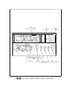
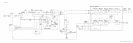
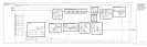
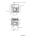
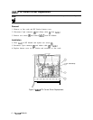
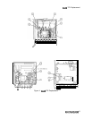
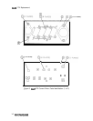
For location of hardware and cables referred to in this procedure, see Figure 2.
Removal
1. Remove ac line cords and RF Section bottom cover.
2. Disconnect connectors
0,
@
and
@J>,
single-pin connector
0,
and double-pin connector
@
from Second Converter.
3. Disconnect the remaining cables from Second Converter:
1 (brown) cable from
.321
OUT
0J
4 (yellow) cable from TUNE
@
4. Remove ACLU cover-plate by removing four screws
@
as shown in View A.
5. Disconnect five connectors a@>, three 92 (white/red) single-pin connectors
a@,
and one
8 (gray) single-pin connector
(iJo.
6. Release ACLU by removing two screws @@ shown in View B.
Installation
7. Secure new ACLU on mounting bracket with two screws
@@,
and reconnect the cables
and wires removed in step 5.
8. Replace ACLU cover-plate with four screws
@
shown in View A.
9. Reconnect the following cables to Second Converter: (Refer to View A.)
1 (brown) cable to
.321
OUT
0
1 (brown) cable to
.321
IN
@
4 (yellow) cable to TUNE
@
10.
Replace bottom cover and ac line cords.
4
A6A7/A6AS/A6A6