


A6A12
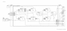
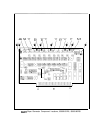
A6A12 YIG-Tuned Mixer (YTX) Driver, Circuit Description
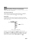
The YTX Driver receives a voltage proportional to the instrument LO frequency and produces
a signal to control current in the YTX coil.
Input Differential Amplifier
@
This input signal to the YTX Driver comes from the A19 DAC and is -3
V/GHz.
For
example, as the YTO Loop sweeps from 2 to 6 Ghz, this input signal sweeps from -6 to
-18 V. It is buffered by differential amplifier
UlA,
and appears at
TPl.
Bandswitch
@
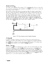
The frequency that the YTX is tuned to must be made to follow the first, second, third,
or fourth harmonic of the YTO frequency, depending on the frequency band in which the
instrument is operating. This is done by attenuating the buffered input signal with a voltage
divider as shown in Figure 1.
R5
TPl
2K
-3V/GHz(LO)
0
0
R7
1K
R8
1K
*
-.525V/GHz(YTX)
0
R9
1K
0
RlO
1K
Figure 1. Bandwidth Voltage Divider
The position on the attenuator is determined by the harmonic number in use. The
bandswitching is done with FET
Ql,
Q2, Q3, and
Q12.
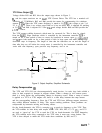
The bandswitch information used to
turn on the
FETs
comes from
A6All
Slope Generator. R6 and
Rll
to R14 form a second
voltage divider used as a gate return through R15 to R18. This prevents current through
bandswitch diodes and resistors (for example,
R19
and
CRl)
when the associated FET is
switched off from affecting the bandswitch voltage divider R5 and R7 to RlO.
A6A12
1