


Summing
Amplifier
@
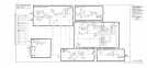
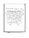
U3 is a noninverting integrator which responds to the voltage at the loop summing point,
the junction of C22 and R43. The output of U3 is connected through R45 to the output
summing network, whose output tunes the AlOA5 PLL2 VCO. Non-zero voltages at the loop
summing point will therefore cause the VCO frequency to change, until the current from the
discriminator reaches a level which cancels the other input, returning the summing point
voltage to zero. In this way, the VCO frequency is forced to be exactly proportional to the net
current fed to the summing point.
Pretune
@J
The pretune circuit tunes the discriminator loop approximately to the desired frequency. The
phase lock loop then applies small corrections to get the frequency exact. A
lo-bit
binary
word representing the pretune frequency is latched by
U9
and U12. The data programs
DAC
Ull,
whose output goes to UlO. If the input is all zeros, the output of UlO is zero.
The pretune current is then that which flows through R40: -1.5
mA.
This tunes the input
frequency to 300 kHz. A binary word representing decimal 1000 will result in
+6.84
V at
UlO’s
output, adding
+0.5
mA
to the summing point. The resulting -1.0
mA
tunes the loop
to 200 kHz.
Scan
Attenuator
@
The attenuated scan ramp is fed to the loop summing point via the range resistors selected
by analog switches
UlA
and
UlD.
If
UlD
is closed, a
+lO
V ramp causes a 0.5 MHz span
(referred to the 15 to 30 MHz VCO output).
UlA
closed results in a 5 MHz span.
UlB
is
closed when
UlA
is, feeding a current to the summing point which compensates for drift and
nonlinearity in
UlA.
U2A and U2B direct the scan ramp directly to the VCO. This “forward feed” helps
compensate for the rather slow response of the discriminator loop.
U2C and U2D perform a logic function:
U2-10
HI,
U2-15
LO for wide scans;
U2-10
LO,
U2-15
HI for narrow scans, and both HI for scan disabled.
Output
Current
Source
@
Ql
and Q2 form a low-noise current summing point for error signals from U3 and forward feed
from the scan and phase lock inputs. The output current goes to the AlOA5 PLL2 VCO.
2
AlOA8