


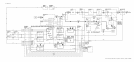
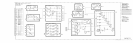
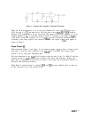
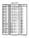

Figure 1. Variable Gain Amplifier, Simplified Schematic
When the 20 K potentiometer is set to zero, the amplifier has a gain of
+1/2;
when set to
20 K, the gain is
-l/2;
and when set to 10 K, the gain is zero.
FETs
Ql
to
QlO
switch in
different 20 K potentiometers for the five bands. The outputs for the two segments at U2 are
summed together in
Ul.
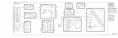
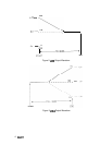
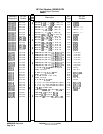
A waveform similar to Figure 2 is present at the output of
U2B
if
a full band is swept (for example, 5.8 to 12.5 GHz), and the oscilloscope horizontal input is
connected to the sweep output of the analyzer. Similarly, the output of U2A will appear as
shown in Figure 3.
Slope Output
@I
Both waveforms (Figure 2 and Figure 3) are summed together at
Ul
to form a current source
with Q16 to drive the slope attenuator in the A6A3 Last Converter. The average output
current is set by slope gain adjustment R84.
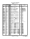
The slope attenuator in the A6A3 Last Converter varies the gain of the 21.4 MHz IF with the
collector current of
Ql6
providing gain correction that varies with frequency. Within each
band, there is independent control over two halves of the band, and IF gain that increases or
decreases with increasing frequency.
When Band F (external mixer) is selected,
QlS
and
Q21
provide additional gain to make up
for the conversion loss of the external mixer.
A6All
3