


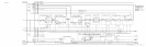

Troubleshooting Information
Troubleshooting Table
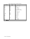
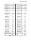
Table 1 correlates CRT phase-lock error messages with the probable faulty phase-lock loop
and associated assemblies. This is especially helpful in determining the faulty loop when more
than one phase-lock error message is displayed.
Table 1. Troubleshooting Using CRT Unlock Messages
Message
Probable Faulty Loop Associated Assemblies
(UNLOCK)
PLl
Phase Lock Loop 1
AlOAl
to
AlOA4
PL2
Phase Lock Loop 2
AlOA5
to
AlOA8
REF
Reference Loop
A7A1,
A7A2,
A22
YTO
YTO Loop
A19, A20, A21, All
M/N
M/N Loop
A7A3,
A7A4
HET
Heterodyne Loop
A6A9,
A6A4
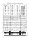
PLl,
PL2
Phase Lock Loop 2
AlOA5
to
AlOA8
PLl,
YTO Phase Lock Loop 1
AlOAl
to
AlOA4
PLl,
PL2, YTO Phase Lock Loop 2
AlOA5
to
AlOA8
REF,
PLl,
PL2
Reference Loop
A7A1,
A7A2,
A22
REF, M/N, YTO Reference Loop
A7A1,
A7A2,
A22
M/N, YTO M/N Loop
A7A3,
A7A4
HET, REF Reference Loop
A7A1,
A7A2,
A22
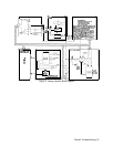
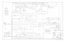
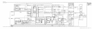
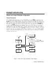
Start Frequency Tuning Equations and Phase Lock Troubleshooting
General
Phase-lock loop troubleshooting is much easier if it is understood how the start frequency
is derived. The Diagnostic Functions of the spectrum analyzer can also be used to simplify
troubleshooting of the phase-lock loop.
The simplified block diagram at the back of this chapter shows the assemblies involved in
setting the start frequency. The HP 8566B has two tuning modes. For frequency spans
greater than 5 MHz, a method called lock and roll is used. This basically involves phase
locking the analyzer start frequency during the retrace period prior to the beginning of a new
scan. For frequency spans of 5 MHz and less, the YTO Loop is phase-locked during all of a
sweep, and the stable
20/30
Loop PLL2 is swept.
4 Analog Troubleshooting