


the two front panel INSTR CHECK LEDs turn on when the LINE switch is set to ON
and within a few seconds turn off (indicating no digital problems), but symptoms (such as
improper CRT display or improper response to particular commands) indicate that the
problem is in the digital area, a “LONG POP” can be performed. LONG POP is very
similar to the normal POP except an additional processor check is performed, all of the
RAM locations in Digital Storage (A3A4 Memory) are checked, and the memory (RAM) on
the Al5 Controller is verified.
Since these more extensive checks require altering information that has been stored in
RAM, LONG POP requires an internal jumper on the Al5 Controller. To perform a LONG
POP:
n Set the LINE Switch to STANDBY.
n Place a jumper between ST or STS to T3
q On Al5 Controller (HP part number 85660-60209) jumper
A15TP4
(STS) to
A15TPl-7
(TV
c7
On Al5 Controller (HP part number 85660-60245) jumper
A15TPl-9
(ST) to
A15TPl-8
(T3).
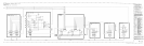
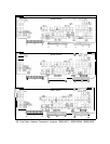
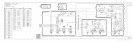
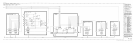
q (Refer to Al5 Controller Component Location Diagrams for location of test points).
n Set the LINE switch to ON.
When LINE switch is then set to ON, the two red INSTR CHECK LEDs are forced on and
the main processor steps through the Self Test routine, expanding the normal POP by the
additional tests mentioned. The expected results for a LONG POP are exactly the same as
for the normal POP of INSTR PRESET
as described above under “Front Panel INSTR
CHECK I and II
LED?.
Because LONG POP is a “destructive test” (it alters any information that has been stored
in RAM), it should be performed only as a last resort effort in troubleshooting what
appears to be a memory or processor-related problem.
Al5
Controller
Self
Test
The Al5 Controller Self Test is run on power-up and after pushing the (INSTRUMENT PRESET]
key. Fourteen
LEDs
(A15DSl
through A15DS14)
on the Al5 Controller give an indication of
the Self Test results. All 14 LEDs are forced on whenever the instrument is turned on or the
(INSTRUMENT PRESET) key is pushed. The main processor (A15U26) then performs a check of
itself, a check of the Peripheral Interface and Timer chip, a checksum verification of all the
ROMs on the Al5 Controller, a read/write check of the
RAMS
on the Al5 Controller, and an
Instrument Bus check that checks the I/O Bus, Address Bus, and Data Bus for stuck lines.
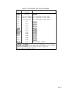
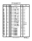
If
all
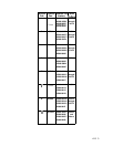
the checks pass, the 14 LEDs are turned off serially as each check is completed. If the
checks fail, one or more LEDs remain on. Refer to Table 1, “A15 Controller Self Test Fail
Indicators,”
at the end of this troubleshooting section.
Other failure modes to look for are:
a. If the 14
LEDs
turn on but are all turned off at the same time (instead of sequentially), the
Peripheral Interface and Timer chip has most likely failed.
b. When an I/O failure is indicated (DS3, DS4, or a combination of these LEDs remain on), it
may become necessary to use an oscilloscope to locate a stuck line.
A15
5