


Note:
The logic negation symbol (0) 1a one gives no information about the actual voltage levels used
in a digital cirucit. For this reason the type of logic system (positive or negative) must be
specified. In this manual, unless otherwise noted on the schematic, the logic system is positive;
that is, the more positive voltage level is the HIGH or l-state and the less positive level is the
LOW or O-state.
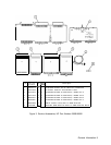
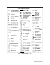
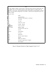
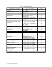
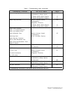
Function Labels
c
Adder
D Amplifier/Buffer
14 Monostable Multivibrator (One-Shot)
&
And Gate
21
Or Gate
=l
Exclusive or Gate
X-Y
Encoder, Decoder
XMAX+Y
Priority Encoder
greek symbol
Schmitt Trigger
ALU
Arithmetic and Logic Unit
CTR
Counter
DEMUX
Demultiplexer
FF
Flip-Flop
MUX
Multiplexer
RAM
Random Access Memory
REG
Register
ROM
Read Only Memory
SAR
Successive Approximation Register
SR
Shift Register
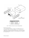
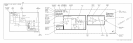
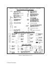
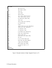
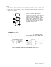
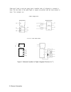
Figure 6. Schematic Symbols for Digital Integrated Circuits (3 of 7)
General Information 15