


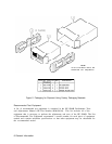
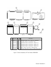
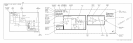

Major Assembly and Component Locations
Major assembly and component location illustrations for the RF Section are located at the
rear of this manual.
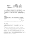
Troubleshooting
Troubleshooting information for the RF Section is divided into three levels as follows:
W
Instrument Level
Spectrum Analyzer Overall Troubleshooting
w
Section Level
RF Section Analog Troubleshooting
RF Section Digital Troubleshooting
A6 RF Module
A7 M/N-Reference/A22 10 MHz Frequency Standard
A10
20/30
Synthesizer
All YTO Loop
n Assembly Level
Most assemblies have troubleshooting hints immediately following circuit descriptions.
Troubleshooting information is also located on assembly level block diagrams, notes, and
schematics.
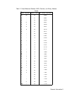
All assemblies are indexed by tab except for the ones listed below. The index tab they can be
found under is also listed.
Table 1. Assembly Locations
Assembly
Location
A24
I
General Parts Listing
I
Tl
A8 Rectifier/AS Power Line Module
Printed Circuit Board Edge Connector Contact Cleaning
Materials
w
Lint-free cloth or equivalent (HP Part Number 9310-0039, Check Digit 3).
w
Solution of 80% electronics-grade isopropyl alcohol and 20% water.
w
Static-free work station.
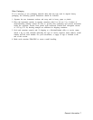
Procedure
1. Dampen the cloth with the alcohol and water solution and scrub the edge connector
contacts vigorously, using a circular motion. Polish one side of the board at a time until
the contacts shine, keeping the cloth damp to dissolve contaminants and reduce static
electricity.
General Information 3