


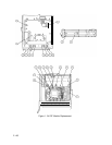
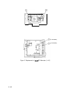
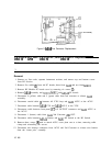
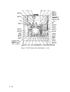

Figure 5.
A6A6
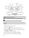
First Converter Replacement
(2 PLACES)
A6A15
3.6
GHz
BPF,
A6A16
LPF, and
A6A18
LPF Replacement
Note
3
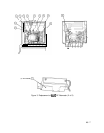
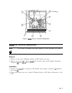
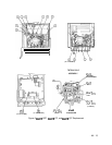
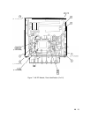
For location of hardware and cables referred to in this procedure, see Figure 6.
Removal
1. Remove ac line cords, separate instrument sections, and remove top and bottom covers
from RF Section.
2. Remove five cables
Q)
from A6 PC boards; three from A6A9 and two from A6A12.
3. Remove RF Module PC board cover by removing six screws
0.
4. Remove A6A9 assembly and A6A10, A6A11, and A6A12 PC boards.
5. Disconnect 4 (yellow) cable and 5 (green) cable from 2nd converter to release A6A9
assembly.
6. Disconnect coaxial cable
@
between All YTO Loop and A6A5 ACLU at the ACLU.
7. Disconnect cable between A6A8 YTX and A6A5 ACLU at the YTX.
8. Disconnect cable between front-panel 1ST LO OUTPUT connector and A6A5 ACLU at
the ACLU.
9. Disconnect 1 (brown) cable from A6A4 2nd Converter
.321
OUT.
10. Disconnect cable between A6A14 Limiter and
A6Al
RF Switch at the RF Switch.
11. Remove three screws
@
used to attach ACLU cover plate one at a time, removing cable
clamp and reinstalling the screws.
12. Disconnect wire harness connectors from ACLU and 2nd Converter to release wire harness
from the “totem pole” assembly.
10 A6