


RF
Section
Internal
Fuse
Replacement
Note
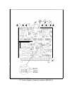
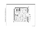
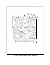
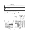
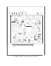
For location of hardware and cables referred to in this procedure, see Figure 1.
Warning
Remove ac line cord from both instruments before proceeding with this
procedure.
1. Position instrument upside-down as shown in view A.
2. Remove feet
@
from rear of RF Section by removing screws
@
shown in view A.
3. Remove bottom cover by loosening screw
@
and pulling cover toward rear of instrument.
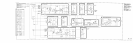
4. Location of fuses is shown in view B.
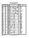
Fl
+22V
1A
\
*
,
RE&
I ER
Fl
+12V
1A
Fl
-5.2V
2.5A
F2
+2OV
3A
F2
-40V
1.5A
F3
t5.2V
6A
F3 -lOV 5A
--
Al7 Al8
POS REG NEG REG
VIEW A
VIEW B
Figure 1. Internal Fuse Replacement
2 A18