


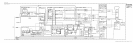
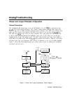

reference (fzoise) from PLL2 in the
20/30
Loop which is either applied directly to the YTO or
divided down and summed into PLL2 and
PLLl
and then applied to the YTO.
When the frequency span is less than 25 kHz, the loop gain of the YTO Loop is increased
by approximately 10 dB to provide better performance. This is performed by control signal
HYGH (High = YTO Loop
G
ain
High) being placed in a High state.
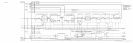
20/30
Loop
(AlO)
The
20/30
Loop translates tuning data for the seven least significant digits of the YTO
frequency (2 to 6.2 GHz) into frequencies from 30 to 20.000 001 MHz. This translation is
quite straightforward and the resulting output frequency can be calculated by the following
equation:
f2c,/ao=
30
-
xxxx
xxx MHz
where
xxxx
xxx is the seven least significant digits of the YTO frequency.
This process of frequency translation is used to tune the YTO over a 10 MHz range in 1 Hz
steps (1 Hz steps in zero frequency span) and uses three complete phase-lock loops
(PLLl,
PLL2, and PLLS) to achieve this.
Phase Lock Loop 2 (PLL2)
p
rovides
a low-frequency (20 to 30 MHz) reference (fze,se) to
the YTO Loop for frequency spans between approximately 100 kHz and 5 kHz. This loop is
locked at the start of each sweep, the error voltage stored in a capacitor, the loop unlocked,
and a sweep taken. For frequency spans of less than approximately 100 kHz and greater
than 5 kHz, the 20 to 30 MHz output is divided by 5 and applied as an input to Phase Lock
Loop 3
(PLLS)
and Phase Lock Loop 1
(PLLl).
Th
e output of
PLLl/PLLS
then serves as
the reference input
(f20,30)
to the YTO Loop. If the frequency span is 5 kHz or smaller, the
output of PLL2 is divided by 100 and applied to PLL3.
Heterodyne Loop (Part of A6)
The Heterodyne Loop (A6A9)
consists of a 3.3 GHz oscillator located in the A6A4 Second
Converter that is locked to the 100 MHz VCXO in the A7A2 assembly. The 100 MHz
signal drives the Sampler in the A6A9 Phase Lock assembly which produces a dc output
proportional to the phase difference between the 33rd harmonic of 100 MHz and the 3.3 GHz
oscillator output signal being sampled. This dc output is amplified and used to drive the 3.3
GHz oscillator to achieve phase lock. If the loop is unlocked, a search oscillator (in the A6A9)
turns on and sweeps the 3.3 GHz VCO until phase-lock is again achieved. The Heterodyne
loop is used only for start frequencies of less than 2 GHz.
Analog Troubleshooting 3