


A8/A9
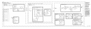
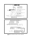
A8 Rectifier, Circuit Description
Power is supplied to the instrument through the A9 Power Line Module, which contains
the line voltage selector, to the primary of transformer
Tl.
Three bridge rectifiers and one
center-tapped secondary provide the rectified outputs.
Diodes CR1 through CR4 form a bridge rectifier that provides approximately 55 V for the
-40 V supply, part of the A18 Negative Regulator. CR5 through CR8 form a bridge rectifier
that provides about 20 V for the -10 V supply and the -5.2 V supply, also part of the Al8
Negative Regulator.
Diodes CR9 through CR12 form a bridge rectifier that provides approximately 30 V for the
i-22 V supply, part of the A8 Rectifier, and also the i-20 V and i-12 V supplies, part of the
Al7 Positive Regulator. Diodes CR13 and CR14 form a full-wave rectifier that provides about
12 V for the
i-5.2
V supply, part of the Al7 Positive Regulator.
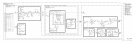
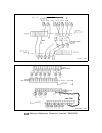
The
+22
V (STANDBY) supply is an 18 V three-terminal regulator
Ul
which has its common
terminal biased at
+4
V by
Rl,
DSl,
and R2.
DSl
is an LED indicator that indicates the
presence of
+22
V.
VRl
and CR16 form a crowbar circuit for overvoltage protection. Fuse
Fl
provides overcurrent protection. The regulator
Ul
is also internally protected against short
circuits on its output. The
+22
V supply is on whenever the instrument is connected to an ac
line outlet.
The instrument is also protected against line overvoltages by an input crowbar circuit
consisting of VR2 and CR18. This crowbar causes the line fuse to blow if an overvoltage
condition occurs on the line.
Filter capacitors and bleeder resistors for all the switched power supplies are located on the
A23 Motherboard. The filter capacitors for the
+22
V (STANDBY) supply are A8C6 and
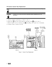
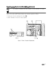
A6AlO C8. The location of fuses in the RF Section is shown in Figure 1.
A8JA9
1