


A21
A21
FM
Coil
Driver,
Circuit
Description
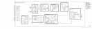
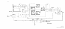
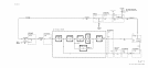
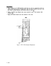
The A21 FM Coil Driver performs two functions.
1. Separates the low-frequency component from the error voltage input (DET IN) and directs
it to the A20 Main Coil Driver.
2. Provides drive current to the FM Coil of the YTO proportional to the high-frequency
component of the error voltage input (DET IN).
Phase Detector Buffer
@
This buffer drives both the low-frequency
(<lOO
Hz) portion of the error voltage input (DET
IN) to be applied to the A20 Main Coil Driver and the high-frequency portion to be applied
to the FM coil of the YTO.
100
Hz
High-Pass
Filter/Amplifier
@
This filter/amplifier separates the low-frequency (<lOO Hz) signals from the input to be
applied to the main coil of the YTO and amplifies the high-frequency signals to be applied to
the FM Coil of the YTO.
Bias
Stabilization
@
This circuit adjusts the dc current in Buffer
@
to ensure there is not quiescent current applied
to the YTO FM Coil.
Output
Amplifier
@
Ql
and Q4 form a push-pull amplifier to provide drive current to the YTO FM Coil
porportional to the high-frequency error voltage input (DET IN). This is done to tune the
YTO frequency to a corrected output determined by the YTO Phase Lock Loop.
Matching
Network
@
Provides impedance matching between the Output Amplifier and the YTO FM Coil to assure
accurate tuning of the YTO frequency.