


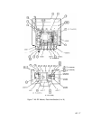
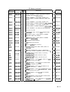
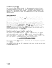
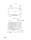

21.4 MHz Preamplifier
0
The 321.4 to 21.4 MHz converter drives the 21.4 MHz preamp which consists of Q6 and
its associated components. Q5 provides bias for Q6 by setting the base current. LlO, C22,
and C23 form a series resonant circuit producing a notch in the frequency response of this
amplifier at 10.7 MHz. This is to prevent the second harmonic of 10.7 MHz from causing a
spurious response.
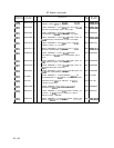
Slope Attenuator
@
The HP 8566 is a harmonic mixing spectrum analyzer, and as such has five bands of
frequencies to cover the range of 0 to 22 GHz. When changing from band to band, the
conversion loss of the input mixer changes. Also within each band there are variations of
conversion loss with frequency.
The variations of conversion loss within each band are compensated by pin diodes CR1 to
CR4 and associated circuitry. Pin diodes have a property of changing RF impedance as
their dc current is varied. Thus
CRl/CR2
and
CR3/CR4
form the two elements of a voltage
divider. The current through
CRl/CR2
is fixed by RlO and
Rll.
The current through
CR3/CR4
is determined by circuitry on the
A6All
Slope Generator. This forms a current
controlled variable attenuator. Pin diodes
CRl/CR2
are used in place of a fixed resistor to
provide temperature tracking with
CR3/CR4.
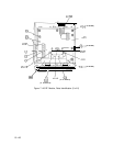
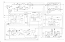
Step Gain Amplifier 1
@
and Step Gain Amplifier 2
@)
The variations of conversion loss from band to band are compensated for by two identical
variable gain amplifiers made up of Q3 and
QlO
and associated circuitry (Q4 and
Q9
are
emitter follower buffers). A simplified circuit of one of these stages is shown in Figure 1. The
gain of the amplifier is determined approximately by the following equation.
Gain
M
Impedance (CR8, CR9, and CRlO)
Impedance (CR5, CR6, and CR7)
The impedance of CR8, CR9, and CR10 is determined by R23 and temperature compensation
circuitry
(Ql).
The impedance of CR5, CR6, and CR7 is determined by the current from the step gain circuit
on the A6AlO Relay Driver.
2
A6A3