


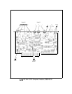

Phase Frequency Detector
@
and Preamplifier
@
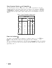
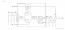
The Phase/Frequency Detector outputs pulses whose width is proportional to the phase
difference of the two input signals. These pulses are filtered by the combination of
R24/C5
and
R25/C6.
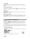
The Preamplifier amplifies these pulses which are representative of the phase
difference of the two input signals. Typical voltage levels for the Preamplifier are shown in
Table 2.
Table 2. Typical Preamplifier Voltage Levels
Voltage Levels
1
Ql
Emitter
Base
Collector
Q2
Emitter
Base
1
Collector
Phase Locked
T
-0.2 -1.c -1.0
-1.t
-0.8 -0.8 -0.8
-1.6
-5.2 -7.9 -7.9
-1.9
-0.2 -1.0 -1.0
-1.0
-0.8
-1.7
-1.6
-0.8
-5.2
-1.8 -1.9
-7.9
No Input At
Jl
J2 J3
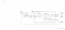
Phase Lock Indicator
@I
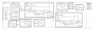
The outputs of the Preamplifier are compared to a reference voltage of -4 V by U2A and
U2B. The output (HULM) is high (ac
t
ive
state) when the loop is unlocked.
This can be checked by disconnecting the 400 MHz input at
A7A3Jl
(96 cable) and measuring
the output of U2 (Pl-26). With the loop unlocked (400 MHz removed), this voltage should be
approximately 4.64 V.
6
A7A3