


AIOAI
AIOAI
Phase
Lock
Loop
1
(PLLI)
Voltage-Controlled
Oscillator
(VCO),
Circuit
Description
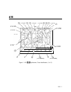
AlOAl
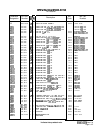
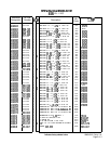
contains the loop amplifier and voltage-controlled oscillator (VCO) for the
PLLl
phase
lock loop. The
PLLl
VCO tunes from 199.9 to 300 MHz (start frequencies of 200.000001
to 300.000000 MHz) for a range of about 4 V to 16 V tuning of the varactor. The
PLLl
VCO drives a counter which divides the frequency by 10. The counter output goes through a
switch and a filter to the
20/30
output. The
PLLl
VCO is turned off in spans greater than
n xl00 kHz but less than or equal to n
x
5 MHz to prevent spurious responses.
Loop
Amplifier
@
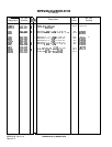
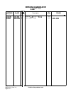
The loop amplifier consists of a low-noise differential pair input stage,
Q9
and
&lo,
and
an operational amplifier U6A. Feedback (ac is
)
p
rovided by C34 and R29. The output
of the amplifier goes through a programmable ac voltage divider consisting of R31, R32,
R33, R34, R35 with R36 and C36. The signal is filtered by a 40 kHz low-pass filter which
has two notches tuned to reject the 50 kHz subharmonics created by fractional-n division
(5 MHz
i
100).
U6B
compares the dc varactor tune voltage to about $17.5 V. If the tune voltage goes higher
than this, U6B switches and pulls it down to about
+5
V. Hysteresis in the switching point
of
U6B
provided by R24 keeps U6B from switching back to the original state until the tune
voltage reaches about
+5
V.
Q2
keeps the tune voltage from going below about
+3
V. This is to ensure that the
PLLl
VCO always oscillates and the varactors do not become forward biased in spans where
PLLl
is active.
Gain
Switch
@
U5 latches the four most significant bits of the programming of the
PLLl
fractional-n divider.
These are level translated by U4 which drives four FET switches. By changing the voltage
divider in
@
in this manner, a constant loop bandwidth of 5 kHz is achieved.
200
to
300
MHz
VCO
@
and
Output
Amplifier
@l
The
PLLl
VCO consists of
Qll
which operates in the grounded-base mode. The resonator is
principally CR3, CR4, and L4. Feedback is accomplished with L5, R16, and C17. In spans
greater than n x 100 kHz but less than or equal to n
x
5 MHz, the VCO is turned off by
forward biasing the varactors. Q5 is a common-base buffer amplifier. The output of the VCO
is applied to Q4 where it is amplified and applied to AlOA3
PLLl
IF and the Divide by 10
0.
In spans of n
x
100 kHz, the VCO is tuned as low as 199.000200 MHz.
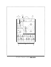
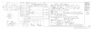
AlOAl
1